Section 5
Theory of Operation
DS-400 - THEORY
OF OPERATION AND DETAILED ANALYSIS
The information contained in this section is considered to be highly technical.
Before attempting to read and understand this section, be advised that
it is written in condensed form. It assumes the reader has been previously
exposed to digital and analog technology. We recommend reading the entire
section first, then go back and review the material in detail. This will
ensure a better understanding of PILL technology.
Engineering Department
INTRODUCTION
PLL synthesizer modifications have become popular in recent years. However,
the actual synthesizer operation is not often explained in detail. CB
radio synthesizers of today have come a long way from the crystal synthesizers
of yesteryear. Understanding PLL operation will allow troubleshooting
of a PLL system to be no more difficult than troubleshooting other common
radio circuitry. Trouble shooting a PLL may seem more difficult at first
because it is a closed loop system. If any part of this loop should fail
(with exception of the oscillator) the result will be the same; an out-of-lock
condition.
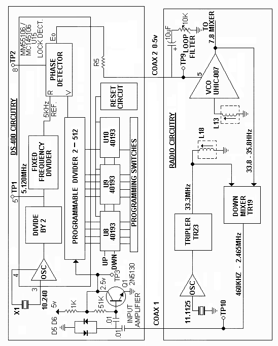
The following pages explain the operation of a PLL synthesizer. In Fig.
31 two large blocks are shown. The D.T.I. DS-400 synthesizer circuitry
is shown in the upper block and the transceiver circuitry is shown in
the lower block. Figure 31 is a block diagram showing the interface between
the radio and 400. The radio circuitry is shown from a Uniden 8719 chassis
with a 11.1125 MHz reference crystal. This chassis is used because of
its popularity on today's market. Operation of most PLL synthesizers is
essentially the same. As the PLL circuitry is analyzed, occasionally refer
back to Figure 31 and the mystery of the phase locked loop synthesizer
will unfold.
