Uniden PC-122
EXPO 100 EXPANDER
MODEL N
UNIDEN PC-122
Installation
|
1. |
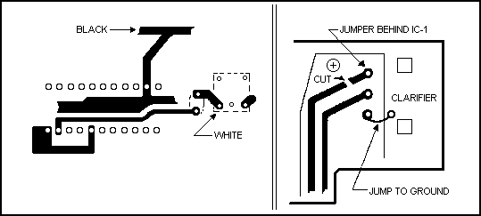
Remove the covers from the unit and locate the coil just to the left of the UPD2824 PLL chip. Solder the expanders White wire to the coil as shown in the diagram below. |
|
2. |
Solder the expanders Black wire to circuit board ground. |
|
3. |
Solder the expanders Red wire to the switched +13.8 VDC found at the volume control. |
|
4. |
Solder the expanders Green wire to the center pin of the clarifier control. |
|
5. |
Looking at the rear of the clarifier control, locate the trace shown in the diagram above and cut it. Solder a wire from the cut terminal of the clarifier, to the jumper wire directly behind IC 1 (right center of unit). |
|
6. |
Solder a short jumper from the bottom terminal of the clarifier to ground as shown in the diagram. |
|
7. |
Locate, and cut, diode D25. unsolder the stripped end of diode D23 from the board. Solder the RF choke (included in kit in series with the diode (also included), to increase slide range. The best result is obtained by tuning the coils for a +3 KHz to -8 KHz result. If this is not obtained, the USB range may be too low in frequency to hit center frequency. The clarifier modification is necessary to make this kit work properly on SSB. ( See Uniden PRO 640e/PRO-810e diagram.) |
Also See:
AM Power = VR-10 SSB Power = VR-6 MOD = VR-5
Diagram:

Copyright CB Tricks -- © 1998. All rights reserved
WARNING! This unit is Not Legal For Class D CB Use In The U.S.A.