Model S
EXPO 100 EXPANDER
Before installing this expander take a few minutes to search out the circuit.
This will help you later in determining how to install it into other units that are similar in design.
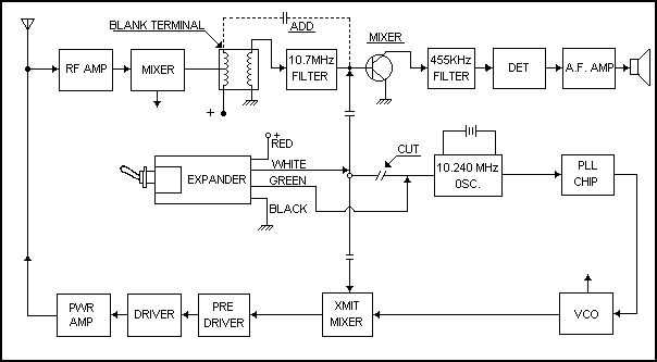
First, locate the 10.695 Mhz crystal filter. This filter often looks like a crystal with three legs on it. The center leg is always ground, the input side will probably connect to a coil, and the output side to a transistor mixer circuit. This is a critical point in installing a kit because the frequency of this circuit has to shift to 10.200 Mhz when the extra channels are operational. The connection points of the 100pf capacitor (included in the kit) must be at optimum to achieve maximum performance without sacrificing the selectivity of the receive section. You may have to experiment a bit to find the best point of connection.
Next, we need to remove the 10.240 Mhz signal from the transmit mixer, and from the second I.F. receiver stage. To accomplish this we will start at pin 4 of the TA7310P mixer IC and trace the circuit backwards. Locate the traces that connect the 10.240 Mhz crystal to the PLL IC and look for a capacitor/resistor (or both) connecting to pin 4 of the transmit mixer. Isolate this trace from the 10.240 Mhz crystal without breaking the connections to the PLL IC. Now you can connect the Green wire from the kit to the 10.240 Mhz crystal, and the expander’s White wire to the isolated capacitor/resistor circuit.
Solder the expander’s Red wire to the +13.8VDC at the On/Off switch, and the Black wire to circuit board ground.
Alignment of the receive coils will be necessary to achieve the best performance on both normal and extra channels. Adjust the 10.695 Mhz coils for best receive while changing the kit band selector switch.

INSTALLATION
|
1. |
Solder the expander’s Red wire to the switched 13.8VDC side of the On/Off switch. |
|
2. |
Solder the expander’s Black wire to circuit board ground. |
|
3. |
Locate the circuit trace from the 10.240 Mhz osc. and cut it. This oscillator circuit feeds the PLL chip, the transmit mixer, and the first receive mixer. The idea is to cut the circuit so that the PLL chip still has 10.240 Mhz, but the receive and transmit mixers are cut free. The White wire from the kit will inject a new frequency into this section, and the Green wire will reconnect them back together when the kit’s switch is in the Normal position. (See Diagram A) |
|
4. |
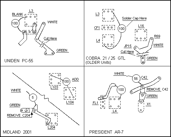
Locate the 10.7 Mhz ceramic filter and solder the small 100pf capacitor (included in the kit) to the points shown in the diagram below. A little experimentation may be necessary to acheive the best receiver performance. The idea is to pass 10.2 Mhz through the filter without degrading the receivers selectivity. Connections will vary with various manufacturers so check with your supplier to see if a diagram is available for your specific needs. |
|
5. |
Tune the 10.695 Mhz mixer coil for maximum signal while switching the kit’s band selector switch back and forth. This will insure that the receive signals will be optimized for best results. |
EXAMPLES

Copyright CB Tricks -- © 1998. All rights reserved
WARNING! This unit is Not Legal For Class D CB Use In The U.S.A.