Model O Alternate Instructions
EXPO 100 EXPANDER
Installation:
|
1. |
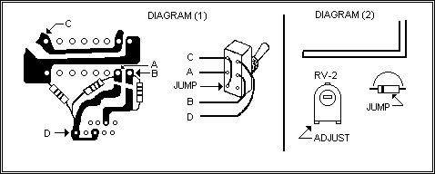
Remove the covers from the unit and locate the PLL02A PLL IC. Using a razor knife, cut the traces of pins 9, and 10, as shown in the diagram below. |
|
2. |
Solder a 2200 ohm resistor across each of the cut traces. Solder another 2200 ohm resistor from the selector side of pin 10, to circuit board ground (pin 16 of the PLL02A). |
|
3. |
Solder a jumper wire across the outer terminals of the DPDT switch, as shown in the diagram. |
|
4. |
Using the ribbon cable provided in the kit solder the points A, B, C, and D from the switch to the PLL chip points labeled similarly. |
|
5. |
Mount the switch in the side of the unit and slighly adjust the VCO coil (Waxed) if channel dropout occurs. |
Notes:
The PLL02A PLL chip has been used in many types of radios for years. This chip can be addressed in several different ways, and therefore, may require a different hookup for a specific type of unit. The ALTERNATE it presented here, is for units that do not work properly using the standard O kit instructons. The above variation should provide approximately the same frequency range on most units. However, the first few channels may be lost on other types.
AM POWER = JUMP DIODE NEXT TO RV-2 AMC = RV-2

Copyright CB Tricks -- © 1998. All rights reserved
WARNING! This unit is Not Legal For Class D CB Use In The U.S.A.