Model L
EXPO 100 EXPANDER
Channel Modification
|
1. |
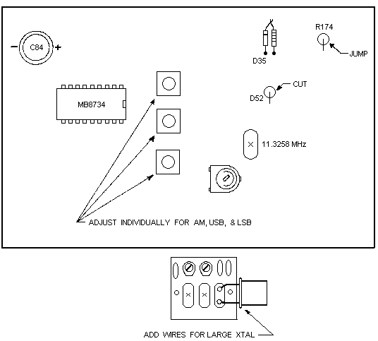
Remove the cabinet from the unit and unsolder the 11.3258 MMz crystal from the circuit board. |
|
2. |
Plug the removed crystal into the expander board and mount the expander by drilling a hole in the cabinet as close to the crystal socket as possible. |
|
3. |
Solder the wires from the expander board to the crystal socket keeping the wire as short as possible. |
|
4. |
Solder wires on the large crystal to make it fit the expander socket. |
|
5. |
Newer models may require replacing capacitor C117 with a 220pf capacitor (included in kit); and tuning coils L20 and L21. This is only necessary if high/low channel oscillation dropout occurs. |
|
6. |
Place the provided label to the side of the switch and position the knob to correspond. |
Slider
|
1. |
Locate resistor R174 on the circuit board and solder a jumper across it. |
|
2. |
Cut the red wire from the fine tune control at the board side and solder it to the (+) side of capacitor C84. |
|
3. |
Cut diode D52. |
|
4. |
Cut the brown wire from the fine tune control (at the board) and solder it to ground. |
|
5. |
Unsolder the stripped end of the varactor diode D35 and solder the provided expander choke in series. |
|
6. |
Newer models may require the removal of resistor R44 to prevent receive/transmit tracking problems. |
Alignment
|
1. |
Turn the unit on and place the expander switch in the normal position, the mode switch to AM, and the clarifier fully clockwise. Using a frequency counter while transmitting, adjust the three coils to the right of the chip to +1 KHz above center frequency. Notice that each of the three coils are separately adjusted for AM, LSB, and USB. |
|
2. |
Adjust each of the trimmer capacitors on the expander board individually for upper and lower channel positions. |
Summary
The unit will now extend far above and below its normal operating range, as well as slide and track with the clarifier control. A slight adjustment of the VCO may be necessary if the unit drops out before reaching its maximum channels.
If trouble is encountered while tuning the normal crystal on frequency, add a 39pf capacitor in series with one of the expander wires and re-align.
Copyright CB Tricks -- © 1998. All rights reserved
EXPO 100 EXPANDER
MODEL L

AM Power = VR10 SSB Power = VR11 Modulation = VR 12
NOTE:
Additional frequencies can be added by changing the MB8734 PLL chip to a MB8719 and adding a SPST switch between pin 10 and ground.
Copyright CB Tricks -- © 1998. All rights reserved
WARNING! This unit is Not Legal For Class D CB Use In The U.S.A.