Cobra 29LTD Classic
EXPO 100 EXPANDER
MODEL A or A +
Cobra 29LTD Classic
Installation:
|
1. |
Solder the expanders RED wire to the +13.8 VDC located at R46 along the front edge of the circuit board. |
|
2. |
Solder the expanders BLACK wire to circuit board ground. |
|
3. |
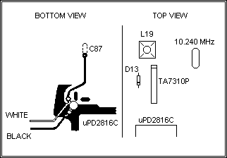
Solder the expanders WHITE wire to capacitor C87. This capacitor is located along side IC-2 (TA7310P), and should not be removed as it is with the regular A kit installation. Solder the WHITE wire to the capacitor on the side away from pin 4 of IC-2 (TA7310P). |
|
4. |
The A Plus kit comes with a diode to replace D13 in the VCO. This is used to broadband the unit's VCO range, and should be installed. The A Plus kit will install directly into the front panel where the FINE TUNE control is located. Remove the existing control, and tape it out of the way. Install the kit so the frequency pads can be adjusted from the top. |
Tuning:
|
1. |
Turn the unit on, and check all channels for operation. Adjust the VCO coil L19 if any of the higher or lower frequencies do not operate properly. |
|
2. |
Put the channel selector on channel 1, and the kit selector switch to the HIGH position. Adjust the kit trimmer capacitor to 27.405 Hhz., and tune coils L17, L20, and L21 for slight power output increase. Turn coils L2 and L3 for best all channel receive. Return to the NORMAL channel position, and check all channels for operation. |
|
3. |
After step two above is completed to insure all channel operation of the VCO a complete power tune can be done for maximum performance... |
REC. = L2, L3 AMC = VR-4 (Cut D11) AM POWER = jump D8 XMIT = L12, LI3, L14
NOTE: Solder the 22pf capacitor included with the kit from the white wire at C87, to ground, if low channels do not work.

Copyright CB Tricks -- © 1998. All rights reserved
WARNING! This unit is Not Legal For Class D CB Use In The U.S.A.