ADDENDUM
INSTALLATION #16
This section describes
the 400 installation to Uniden chassis using the D2824 PLL Chip.
1. Remove the transceiver and 400 cases.
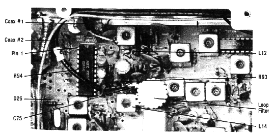
2. Remove R94 (10K) from the radio.
3. Remove D26 from the radio.
4. Remove L12 from the radio and replace with coil supplied in the Mod
Kit.
5. Remove the VCO coil (L14) and replace it with the VCO coil supplied
in the Mod Kit.
6. Remove C75 (47pF) from the radio and replace with 120pF cap supplied
in the Kit.
7. Connect the center of Coax #1 to pin 22 of the D2824 Chip.

Fig. A1 - Uniden D2824 Chassis Parts Location
8. Connect the center
of Coax #2 to TP-2 (JCT of R93 & R94).
9. Loop Filter Installation:
Locate the 10K trimpot and 10uf capacitor supplied with the 400. Solder
the wiper of the trimpot to ground. Install the 10uf capacitor between
one end of the trimpot and TP-2. Observe polarity; the negative (-) of
the capacitor must connect to the trimpot. Keep leads as short as possible.
10. Connect the black wire to radio ground foil near the power supply
or modulator section.
11. Connect both coax shields to ground.
12. Connect the red wire to the on/off voume control for power.
13. To comply with FCC regulations remove TR40.
This completes the installation procedure. Before operation, the 400, must be programmed and the radio must be realigned. Go to the programming section and proceed.
PROGRAMMING INSTRUCTIONS
Uniden D2824 Chassis
| CODE # | PLL CHIP # | REFERENCE
CRYSTAL FREQ. |
NINE-POLE ROCKER SWITCH | DIRECTION | ||||||||
| 1 | 2 | 3 | 4 | 5 | 6 | 7 | 8 | 9 | ||||
| F | F | O | O | F | O | O | O | F | Normal | |||