 Cobra CA-75 Power Microphone series
 Troubleshooting Schematic
Assembly View
Upgrade Changes And
Microphone Wiring diagram
Documentation Project
 Cobra CA-75 Power Microphone series
Troubleshooting Schematic
Assembly View
Upgrade Changes And
Microphone Wiring diagram
Documentation Project
Microphone Identification Page
Courtsey Of Andrew Cody
Miscellaneous Parts and Data Additions
Reference Section and
Modification - Enhancements Section

| Part | Description | Value | Part | Description | Value |
|---|---|---|---|---|---|
| R 1 | Carbon Composition Resistor | 1 K ohm [Brown-Black-Red] 1/6W | C 1 | Electrolytic Capacitor | 100uF 50WVDC |
| R 2 | Carbon Composition Resistor | 11 K ohm [Brown-Brown-Orange] 1/6W | C 2 | Electrolytic Capacitor | 0.22uF 50WVDC |
| R 3 | Carbon Composition Resistor | 10 K ohm [Brown-Black-Orange] 1/6W | C 3 | Electrolytic Capacitor | 0.47uF 50WVDC | R 4 | Carbon Composition Resistor | 100 ohm [Brown-Black-Brown] 1/6W | C 4 | Disc Capacitor | 0.01uF [103 Disc] Type F |
| R 5 | Carbon Composistion Resistor | 18 K ohm [Black-Grey-Orange] 1/6W | C 5 | Disc Capacitor | 0.022uF [223 Disc] Value M |
| R 6 | Carbon Composition Resistor | 3.9 K ohm [Orange-White-Red] 1/6W | C 6 | Disc Capacitor | 150pF [151 Disc] Type YF/M |
| R 7 | Carbon Composition Resistor | 1.8 K ohm [Brown-Grey-Red] 1/6W | C 7 | Electrolytic Capacitor | 10uF 25WVDC |
| R 8 | Carbon Composition Resistor | 12 K ohm [Brown-Red-Orange] 1/6W | C 8 | Disc Capacitor | 0.001uF [102 Disc] Type M |
| R 9 | Carbon Composition Resistor | 2.2 K ohm [Red-Red-Red] 1/6W | C 9 | Disc Capacitor | 0.001uF [102 Disc] Type YF |
| Q 1 | C 1740 NPN Transistor | General purpose Low-pwr Amp ECB | Q 2 | C 1740 NPN Transistor | General purpose Low-pwr Amp ECB |
| VR1 | Potentiometer [Log taper] | 100 K ohm Volume Control | LED1 | LED Lamp T-1 case | Color varies w/year and model |
| SW 1 | 4PDT PTT Switch | Plunger Spring-loaded | MIC | FET-Electret Condensor | 10mm° 6VDC w/holder |
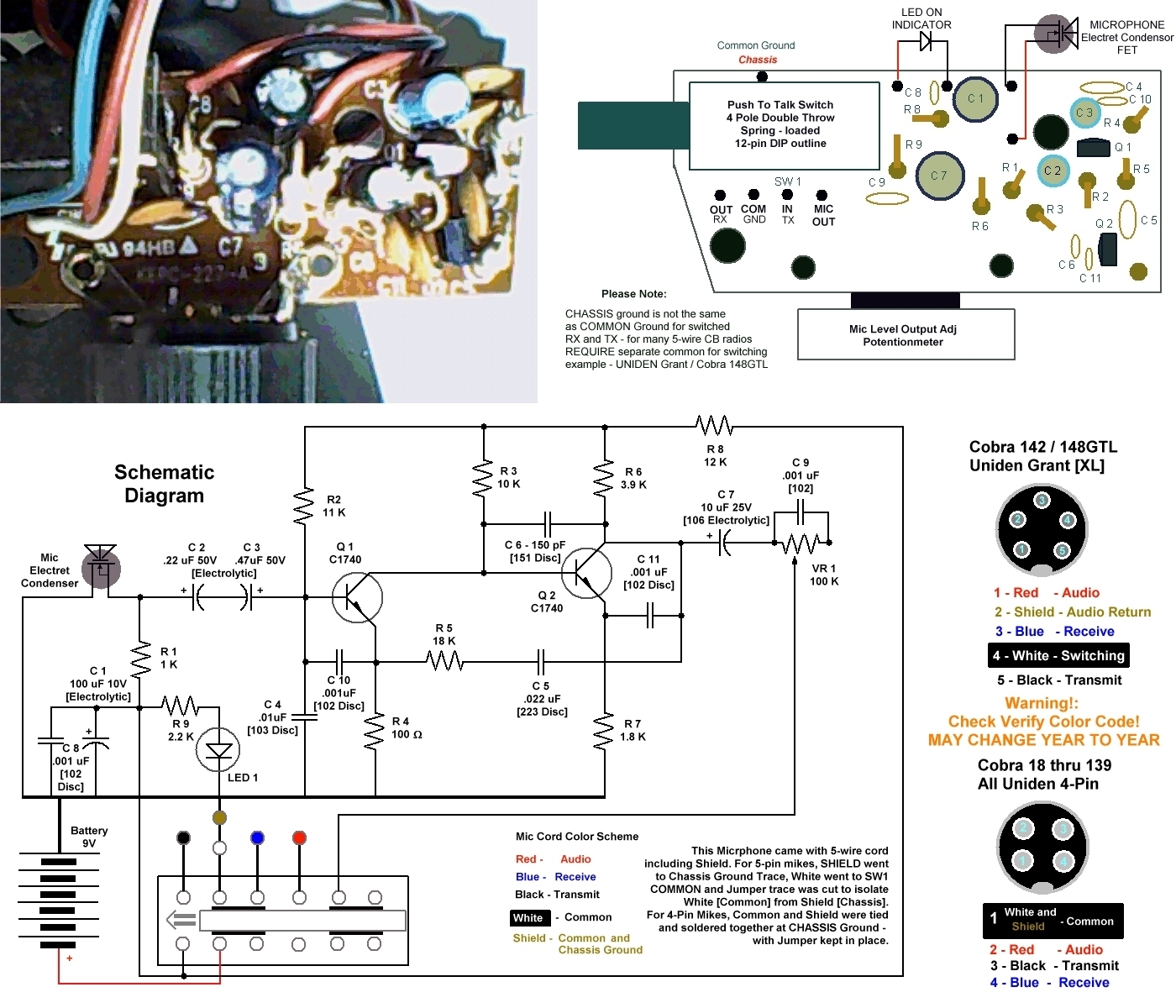
This schematic is based upon the CA-75 and NEWER Cobra M-75 series of microphones. Cobra went to a 3-vent/partition face to make the mic more omni-directional while the single-windscreen mikes remain more carloid, or directional in pickup.
Powered by a 9 Volt source switched on by depressing the plunger of SW1. The voltage is applied to the circuit through a pair of filter caps C8 and C1, to reduce pop, noise and switching transients that may be caused by high RF-noise environments or dirty/heavily used sliding contacts of the plunger.
LED 1 - is biased using R 9 to show battery-good condition. R 9 and R 8 are selected not just to limit current to the circuit or from overdrving the LED, it also serves as a battery-condition monitor. If the battery is weak or drained - the load on this circuit would be too-low to light the LED and the resistance through R 8 would prevent the amp from functioning.
The Microphone Element is an FET-based Electret Condensor which requires power. The use of R 1 provides power to the device and some working impedance to the output which is developed and sent through two Electrolytics arranged back-to-back to form a non-polarized capacitor that has an arbitrary working total capacitance between 0.15uF to 0.19uF.
The purpose of the back to back arrangement is two-fold - to reduce audio drive and offset problems with DC-bias provided to Q1 with R 2. C 4 provides a shunt-path filter for audio and RF. The typical frequency response, or bandwidth, of this mic amp is quite wide. Radios' only need a frequency response peak between 600Hz to 1.1KHz and the use of C 6, C 10 and C 11 provides most the roll off needed.
Q 1 is designed as a buffer amp to match the high impedance output of the MIC to develop differential output from Collector to output load resistor R 4. The Collector of Q 1 couples to the Base of Q 2 for a signal generated across Q 2s' Collector to Emitter through load resistor R 7 and Source impedance set by the value of R 6. The difference in values used by R 6/R 7 sets overall output impedance seen by output capacitor C 7.
Q1 is biased as Class A with R 2 and C 10 acting like gain control to R 3 and R 4 - and provides a gain factor of 10. R 2 provides DC bias while C 10 samples Audio developed across R 4 and applies it back to the input as an error-correcting signal for audio and frequency roll-off.
R 2 and C 10 - these two act as feedback, gain control and to provide an active filter network. C 10 is used as a low-pass filter. It has less reactance [lower resistive effect] at higher frequencies producing a roll-off curve to high-end [Treble-range] audio frequencies and is an RF shunt if RF is present.
C 11 is bypass filter adding to the active filter network C 10, C 6, C 5 and R 5.
Q 2 is the output amp, the use of R 7 sets output impedance by working with R 6. The use of R 3 and R 6 is to develop gain and stability by limiting current draw as a Class-A amp, extending battery life. C 6 is another active filter working as a low-pass filter to reduce high-frequency response by providing a similar roll-off curve as with C 10. The collector of Q 2 is the output of the audio and is passed to C 7 and VR 1.
VR 1 provides control of the audio level, and due to inherent filter properties of R/C circuits in series, C 9 is used to " Swamp out " those effects [C 7 and VR 1] and balance the tonal quality across the adjustment range of the potentionmeter.
The use of R 5 and C 5 is for compression of audio frequencies and keeps DC-load voltages from interacting. It's a positive feedback system. The output of one transistor is impressed onto the other through their respective load resistors and controls gain by affecting the operational window of the preceeding stage, changing it's operation into a differential amp [Q 1]. This type of interaction controls voltage gain between the two stages and affects the collectors' outputs with respect to their emitters'.
This effect stabilizes gain in direct-coupled stages.
Providing a means of compression by injecting amplified audio to the load resistor of the preceeding stage generates interaction of extra signal levels being applied to the preceeding stages' load resistor - lowering the voltage drop across it's Collector to Emitter. Using Direct-coupling, the Base Region of the subsequent stage [Q 2] remains at potentials set by R 3 and R 6. It reduces the need for extra filtering at the output. This method effectively lowers the voltage difference between Q 1's Collector to Emitter when strong audio levels are present without inducing severe clipping distortion into the audio waveform.
The largest problem is in the output level of the Electret Condenser element [R 1], the working impedance is 1K and can changed to a higher value - for better results try increasing the values to 2.2K to 3.9K. This increases output, but provides better tonal response to radios that can take a wider range of frequencies and the output gives better tonal quality.
Many people remove one of the two input capacitors C 2 or C 3 and short to a jumper to keep the circuit active.
Better results can be acheived by adjusting load resistor in the first stage, R 4 to a higher value. I personally use 680 ohms to improve working impedance against R 2 and R 3.
An interesting effect similar to how a D104 can sound like can be done by changing R 2 to a higher value. I use 18K to 22K to boost overall gain of Q 1 to Q 2. You will also need to change R 8 to a lower value, between 8.2K to 10K. This will provide more overhead for the circuit to give a better frequency response without impacting battery life.
I discovered this by working on pre-1994 CA mikes - some did not have a resistor installed in location of R 2. The microphone worked, but had a bassy flat sound to it. Putting in a 15K to 18K resistor here improved the fidelity - considerably.
Changing C 6 and C 11 can also improve tonal results - I remove C 6 completely and replace with a 270K [Red-Violet-Yellow] resistor and swap out C 11, replace with C 6 - at C 11.
You do this at your own risk, remember that this is for Educational Purposes Only!
For Maximum Gain and Total Frequency Response Curve Improvement
If you don't understand what the below does, then this whole page isn't going to help you.
Please note that Microphone cords are not a constant - except for being a pain.
If you have ever re-wired a favorite mike to a different radio - then you know what I'm talking about.
I'm refering to color codes and which one of the wires is supposed to be the audio line.
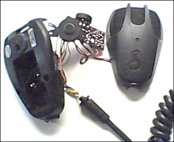
I'm assuming you've taken the covers apart and removed the battery [Please do so] and found and removed the two small phillips head screws holding the mic element and the the board to the rear case.
On a new mike cord, one wire - shield, is wrapped around only one wire and that is the audio wire - it's shielded from all the rest of the wires in the bundle.
Determine for yourself which wire with be Receive, Transmit and Common [for 4 pin radios, it's shield and the black wire - if it exists in the cord color-scheme] and Audio. Shield should ALWAYS be used as Chassis Common Ground and the wire it wraps and protects MUST be your Audio line - if you see the trace side of this mike, you'll note that there is a foil trace on the edge of the PCB that follows around ther perimiter [outer edge] and this is a means to provide some shielding from hum pickup and the mike cords' shield should be used here.
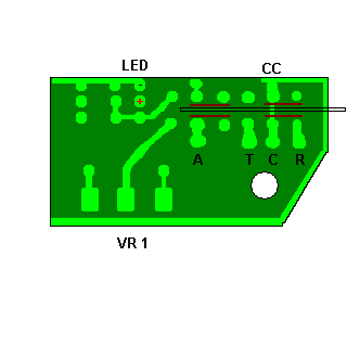
 As a guide, the graphic on the left is a diagram of the 4-pole Dual-Throw switch and how to wire it. The entire board is not shown, nor is it needed here, I'm just describing how to wire a 5-pin or 4-pin to this mike. I'm trying to keep it simple...
The letters A T C R denotes Audio, Transmit, Common, Receive.
CC denotes Common Chassis, Common Ground and the Shield of the Mike wire needs to be used here. Sorry to be redundant folks, but I've experienced a lot of mikes' that didn't work well in Trucks and noisy receive environments simply due to the fact that whomever wired the mike originally didn't plan and follow a standard. They would have saved a lot of trouble if they followed conventional thinking and used Shield where it belongs.
LED and VR 1 help you orient the switch contacts and where they start and end. Each pole has 3 contacts, Two poles on each side, for a total of 4 poles and twelve pins - six of them on each side.
The bark brown/copper color denotes which pins are SHORTED when the PTT switch is OUT and is the normal position - which is the receive.
When you engage the plunger, the switch contacts move to the left in the picture. They disengage one set of contacts and move the wipers of the 4-poles simultaneously over to the left. They engage the other contact and stay connected to the Center set of contacts on all 4-poles at all times. Each pole is electrically isolated from the other so they electrically operate independently but function together.
Some older Realistic radios have the Audio line shorted to ground when the radio is in the receive mode to remove hum-pickup from an open mic line into the Receivers' audio path. Uniden, Cobra and later Realistic radios have the audio line disabled internally by switching diodes instead. I'm pointing this out so you are aware that as you figure out how to wire all the pins to the radio using the mike cord and this mike, and come across a radio that shorts out a set of pins required to get the receive to work right.
Use a desoldering braid or solder-sucker to help remove any excess solder. Its' close quarters in there, so any shorts caused by solder blobs will cause a problem or two.
Desolder all the wires from the Mic cord from the PCB.
If the cord is a 4-wire in good condition, save it for another radio.
I recommend a pre-trial fit with the grommet in place at this time
There is a small push nut on a plastic stem in the center of the handsets' back - the one that contains the battery compartment. Don't remove it, just pry it up a little so you can snug the mike cord wires to it to help in closing the case back up and it acts as a strain relief point when you're putting it all back together.
If you so wish, you can replace the original LED light with any other color to personalize this mike. Just use a T-1 mini style. The T 1-3/4 style case is too large to fit and you'll need to enlarge the hole to accomodate it.
The resistor that powers it, is a 2.2K and should be fine for nearly all of the different single colors. Just remember the resistor [Red-Red-Red] and the hole closest to it is the Positive side [Anode] and the hole at the edge of the board is the return [Cathode or Ground] for it.
This requires a 5-wire mike cord with shield.
Graphic above shows wiring for Cobra 142/148 GTL, Grant and Grant XL and follows pinout per schematic.
Please refer to the page that shows component top and foil trace views if you need help - you'll need to go back to CAindex.html and view the link again if needed.
You should remove as much solder as possible before proceeding.
As in the Graphic above, find the T C R holes and the pins they go to. The pair in the center two may have a shorting jumper in-between the pins at the centerline of the switch [ C to CC ] - cut the trace.
Find the shield and audio wire on the mike cord, shield would be wrapped around that wire only. Solder this to the hole labled CC in the graphic above. It has to go there.
Audio goes to the terminal A shown above.
Because the color-code in the mike cording may be different than the graphic at the top, just remember the pins, Audio Line [A] - Pin 1, Shield and Common Chassis Ground [CC] Pin-2, Receive [R] Pin-3, Common-Switched [C] Pin-4 and Transmit [T] Pin-5 have to be soldered to match the plug side.
Before [Ahemn] you finish stuffing the Mike back together, check wiring and make sure the LED will light.
Before you finish the install, remove the battery for this test.
With the PTT pressed-in, Pin-4 to Pin-3 should show near zero and Pin-5 should be open. Pin-2 should not short to any of the other pins.
Check and fix any binding or scraping. Reassemble the case, tighten screws and replace the battery.
When doing initial checks - use the PA and an external speaker plugged into the PA jack and verify the microphone works. Remember the radios' volume control and Mic Gain settings are affected as well as VR 1 settings on the handset.
Use the above mods with discretion and enjoy the results - or curse them, depending on how you look at it.
I hope the above has enlightened you - and thank you for your participation in visiting this website.
Thank You!
:+> Andy <+:
Disclaimer: Although the greatest care has been taken while compiling these documents,
we cannot guarantee that the instructions will work on every radio presented.
For contact information and corrections please
send a brief Email to Handy Andy
or to the host website; CBTricks.
Thank you.
Return to the CB Tricks Home Page
URL: http://www.cbtricks.com/