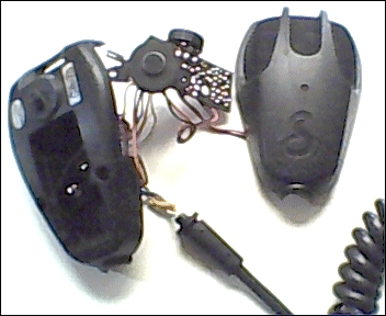
 Cobra CA-75 Power Microphone series
Troubleshooting Schematic
Assembly View
Upgrade Changes And
Microphone Wiring diagram
Documentation Project
 Cobra CA-75 Power Microphone series
Troubleshooting Schematic
Assembly View
Upgrade Changes And
Microphone Wiring diagram
Documentation Project
Board Identification Page
Courtsey Of CBTricks.com
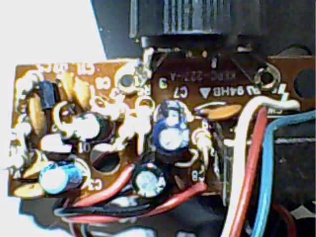
 Top View
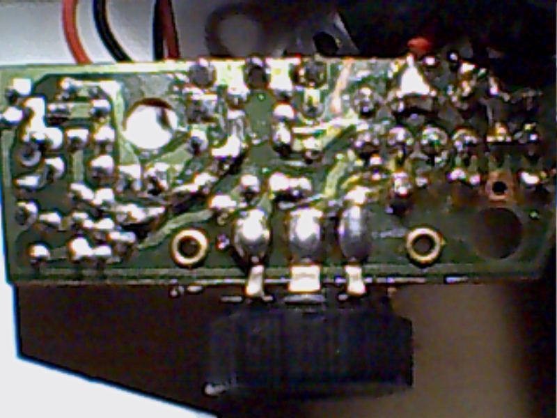
 Bottom view showing traces.
Note the location of the 4PDT switch contacts. One is unused [center contact], locate mounting hole to the far right.
Note the White and Shield tied to Chassis ground near the top right of the picture using a black jumper wire. The red wire next to it is from the battery positive terminal. The black wire soldered across a jumper trace located here is to tie RX and TX switching to common Chassis and battery grounds together back towards the mic cords' entry point into the handset.
Return to CA-75 Microphone page.
Disclaimer: Although the greatest care has been taken while compiling these documents,
we cannot guarantee that the instructions will work on every radio presented.
For contact information and corrections please
send a brief Email to Handy Andy
or to the host website; CBTricks.
Thank you.
Return to the CB Tricks Home Page
URL: http://www.cbtricks.com/